
|

| Brand Name: | VIIPLUS |
| Model Number: | Bimetal Bushing |
| MOQ: | negotiable |
| Price: | Negotiable |
| Payment Terms: | MoneyGram, Western Union, T/T |
| Supply Ability: | casting bimetal bushing, China, manufacturers, suppliers, factory, wholesale, Metric Self Lubricating Bushing, Self Lubricating Bushings, Journal Bronze Bearings, Bimetal With Graphite Bearing, Metallic Bearings, Flanged Bimetallic Plain Bearing |
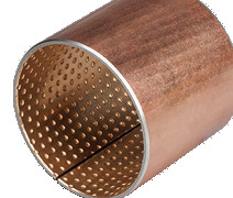
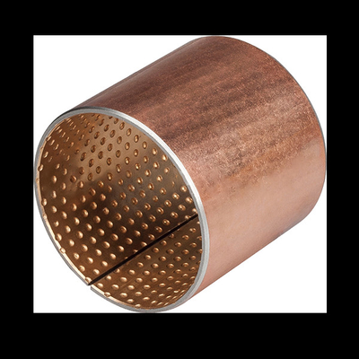
JF800 bimetal bearing bushes, crafted with either CuPb10Sn10 or CuSn6Zn6Pb3 alloys, are specifically designed for engine applications, offering unmatched performance and durability.
The unique bimetal construction combines the strength and rigidity of a steel base with the wear resistance and lubricating properties of the chosen alloy. This ensures smooth and efficient operation, even under high loads and temperatures, crucial for engine components.
The CuPb10Sn10 alloy, known for its excellent wear resistance and load-bearing capacity, is ideal for engines that require high performance and reliability. On the other hand, CuSn6Zn6Pb3, with its good corrosion resistance and self-lubricating properties, is suitable for engines operating in harsh environments or with frequent start-stop cycles.
Our JF800 bearing bushes are precision-engineered to fit various engine designs, ensuring a secure and stable fit. They are also heat-treated to further enhance their hardness and wear resistance, making them suitable for long-term, high-demand operations.
With our commitment to quality and performance, you can trust that our JF800 bimetal bearing bushes will deliver exceptional results in your engine applications. Contact us today to learn more about our products and how they can enhance the performance and reliability of your engines.
Bimetal Bearings Bushings ,Oil Hole Design,Bimetal Cylindrical Bushings,Flange Bearings, Thrust Washer made to order from china.Material (CuPb10Sn10, SAE-797, JIS-LBC3 Bronze Alloy )
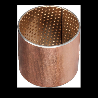
Oil Holes Form
Diamond Form
Smooth ,No Oil Pocket
| Oil Hole is necessary to design if bimetal bushings have lubricated sufficiently; the following oil hole design is recommended, which is also suitable for bimetal series without special requirements. | |||||
| Bushing O.D. (D) | Φ14>D ≤ 22 | Φ22>D ≤ 40 | Φ40>D ≤ 50 | Φ50>D ≤ 100 | Φ100>D ≤ 180 |
| Oil Hole Diameter (mm) | 3 | 4 | 5 | 6 | 7 |
| Bimetal Bearings Oil hole location should keep away from the split gap & loading area, and in favor of oil-taking. | |||||
| Chemical composition mass /% | |||||||||
|---|---|---|---|---|---|---|---|---|---|
| Cu | Sn | Al | Fe | Mn | Ni | Pb | Si | P | Zn |
| 78.0-82.0 | 9.0-11.0 | 0.01 | 0.25 | 0.2 | 2 | 8.0-11.0 | 0.01 | 0.1 | 2 |
We can produce precise finished parts according to customers' special requirements and drawings.
Sintered SAE797 Layer + Steel Backing + Copper Plating / Tin-Plating
JF800 bimetal bearings are steel and copper alloy products with low carbon steel plate as the matrix material and sintered CuPb10Sn10 or CuSn6Zn6Pb3 on the surface. The bimetlal t is a double alloy bearing bearing capacity of the strongest one, heavy vehicle balance bridge bushing, gasket; The slave wheel of a bulldozer; Automotive steel bushing, all used in this product. It is a widely used high - load low - speed sliding bearing.
We can design bimetal bearings according to the operating conditions of copper alloy surface processing of various types of oil tank, oil hole, hole, etc., in order to suit to cannot continue to go hard or go occasion. Good bonding strength and optimum bearing capacity can be obtained by secondary sintering and secondary extrusion.
![]()
![]()
| Maximum dynamic load | 140P N/mm² | MAX Temperature°C | Grease lubrication | 150°C | |
| Maximum linear velocity | Grease lubrication | 2.5Vm/s | Fluid lubrication | 250°C | |
| MAX PV | 2.8N/mm². m/s | Match the diameter of axle | HRC | ≥ 53 | |
| μ | 0.05~0.15 | Ra | 0.16~0.63 | ||
| Maximum linear velocity | Fluid lubrication | 10 | Alloy layer hardness | 80~120 | |
| MAX PV | 10 | Coefficient of thermal conductivity | 47W/mk | ||
| μ | 0.04~0.12 | Linear expansion coefficient (axial) | 18×10-6/K | ||
Norminal Thiickness |
Tolerances of Series B (non-machinable) |
Tolerances of Series C (non-machinable) |
| 1.0 | -0.025 | +0.25 +0.15 |
| 2.0 | -0.030 | +0.25 +0.15 |
| 2.5 | -0.035 | +0.25 +0.15 |
| 3.0 | -0.040 | +0.30 +0.15 |
| 3.5 | -0.045 | +0.30 +0.15 |
| 3.5 | -0.050 | +0.30 +0.15 |
|
d
|
D
|
相配轴径
公差( h8)
|
相配座孔
公差(H7)
|
压入H7座孔
内径公差
|
Wall thickness
壁厚
|
注油孔
|
f1
|
f2
|
L 0
-0.40 |
||||||||
|
min
|
max
|
10
|
15
|
20
|
25
|
30
|
40
|
50
|
60
|
||||||||
|
10
|
12
|
10-0.022
|
12+0.018
|
+0.148
+0.010 |
0.995
|
0.935
|
4
|
0.5
|
0.3
|
1010
|
1015
|
1020
|
|
|
|
|
|
|
12
|
14
|
12-0.027
|
14+0.018
|
1210
|
1215
|
1220
|
|
|
|
|
|
||||||
|
14
|
16
|
14-0.027
|
16+0.018
|
1410
|
1415
|
1420
|
|
|
|
|
|
||||||
|
15
|
17
|
15-0.027
|
17+0.018
|
1510
|
1515
|
1520
|
|
|
|
|
|
||||||
|
16
|
18
|
16-0.027
|
18+0.018
|
0.8
|
0.4
|
1610
|
1615
|
1620
|
|
|
|
|
|
||||
|
18
|
20
|
18-0.027
|
20+0.021
|
+0.151
+0.010 |
1810
|
1815
|
1820
|
1820
|
|
|
|
|
|||||
|
20
|
23
|
20-0.033
|
23+0.021
|
+0.181
+0.020 |
1.490
|
1.430
|
2010
|
2015
|
2020
|
2020
|
|
|
|
|
|||
|
22
|
25
|
22-0.033
|
25+0.021
|
6
|
2210
|
2215
|
2220
|
2220
|
|
|
|
|
|||||
|
24
|
27
|
24-0.033
|
27+0.021
|
1.0
|
0.5
|
2410
|
2415
|
2420
|
2420
|
2430
|
|
|
|
||||
|
25
|
28
|
25-0.033
|
28+0.021
|
|
2515
|
2520
|
2520
|
2530
|
|
|
|
||||||
|
26
|
30
|
26-0.033
|
30+0.021
|
+0.205
+0.030 |
1.980
|
1.920
|
|
2615
|
2620
|
2620
|
2630
|
|
|
|
|||
|
28
|
32
|
28-0.033
|
32+0.025
|
|
2815
|
2820
|
2820
|
2830
|
2840
|
|
|
||||||
|
30
|
34
|
30-0.033
|
34+0.025
|
1.2
|
0.6
|
|
3015
|
3020
|
3020
|
3030
|
3040
|
|
|
||||
|
32
|
36
|
32-0.039
|
36+0.025
|
|
3215
|
3220
|
3220
|
3230
|
3240
|
|
|
||||||
|
35
|
39
|
35-0.039
|
39+0.025
|
|
|
3520
|
3520
|
3530
|
3540
|
3550
|
|
||||||
|
38
|
42
|
38-0.039
|
42+0.025
|
8
|
|
|
3820
|
3820
|
3830
|
3840
|
3850
|
|
|||||
|
40
|
44
|
40-0.039
|
44+0.025
|
|
|
4020
|
4020
|
4030
|
4040
|
4050
|
|
||||||
|
d
|
D
|
相配轴径公差(h8)
|
相配座孔公差(H7)
|
压入H7座孔内径公差
|
Wall thickness
壁厚
|
注油孔
|
f1
|
f2
|
L 0
-0.40 |
||||||||
|
min
|
max
|
25
|
30
|
40
|
50
|
60
|
80
|
90
|
100
|
||||||||
|
45
|
50
|
45-0.039
|
50+0.025
|
+0.205
+0.030 |
2.460
|
2.400 |
8
|
1.5
|
1.0
|
4525
|
4530
|
4540
|
4550
|
|
|
|
|
|
50
|
55
|
50-0.039
|
55+0.030
|
+0.210
+0.030 |
|
5030
|
5040
|
5050
|
5060
|
|
|
|
|||||
|
55
|
60
|
55-0.046
|
60+0.030
|
|
5530
|
5540
|
5550
|
5560
|
|
|
|
||||||
|
60
|
65
|
60-0.046
|
65+0.030
|
|
6030
|
6040
|
6050
|
6060
|
|
|
|
||||||
|
65
|
70
|
65-0.046
|
70+0.030
|
|
6530
|
6540
|
6550
|
6560
|
|
|
|
||||||
|
70
|
75
|
70-0.046
|
75+0.030
|
|
7030
|
7040
|
7050
|
7060
|
7080
|
|
|
||||||
|
75
|
80
|
75-0.046
|
80+0.030
|
9.5
|
|
7530
|
7540
|
7550
|
7560
|
|
|
|
|||||
|
80
|
85
|
80-0.046
|
85+0.035
|
+0.215
+0.030 |
|
|
8040
|
8050
|
8060
|
8080
|
|
|
|||||
|
85
|
90
|
85-0.054
|
90+0.035
|
|
8530
|
|
8550
|
8560
|
8580
|
|
85100
|
||||||
|
90
|
95
|
90-0.054
|
95+0.035
|
|
|
|
9050
|
9060
|
9080
|
|
90100
|
||||||
|
95
|
100
|
95-0.054
|
100+0.035
|
|
|
|
|
9060
|
9080
|
9090
|
90100
|
||||||
|
100
|
105
|
100-0.054
|
105+0.035
|
|
|
|
|
10060
|
10080
|
10090
|
100100
|
||||||
|
105
|
110
|
105-0.054
|
110+0.035
|
|
|
|
|
10560
|
10580
|
|
105100
|
||||||
|
110
|
115
|
110-0.054
|
115+0.035
|
|
|
|
|
11060
|
11080
|
|
110100
|
||||||
|
115
|
120
|
115-0.054
|
120+0.035
|
|
|
|
11550
|
|
11580
|
|
|
||||||
|
120
|
125
|
120-0.054
|
125+0.040
|
+0.220
+0.030 |
|
|
|
12050
|
12060
|
|
|
120100
|
|||||
|
125
|
130
|
125-0.063
|
130+0.040
|
|
|
|
|
|
|
|
125100
|
||||||
|
130
|
135
|
130-0.063
|
135+0.040
|
|
|
|
|
13060
|
|
|
130100
|
||||||
|
135
|
140
|
135-0.063
|
140+0.040
|
|
|
|
|
13560
|
13580
|
|
|
||||||
|
140
|
145
|
140-0.063
|
145+0.040
|
|
|
|
|
14060
|
14080
|
|
140100
|
||||||
|
150
|
155
|
150-0.063
|
155+0.040
|
|
|
|
|
15060
|
15080
|
|
150100
|
||||||
Bi-metallic bushing is formed from steel strips with alloy lining material. The alloy lined surface can be machined oil grooves, holes, formed Indentations etc according to different application. It is suitable for high load, lower speed oscillation & rotation movement.

